All-Digital Frequency Synthesizer in Deep-Submicron CMOS
 -15%
portes grátis
-15%
portes grátis
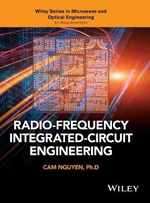
All-Digital Frequency Synthesizer in Deep-Submicron CMOS
Staszewski, Robert Bogdan; Balsara, Poras T.
John Wiley & Sons Inc
09/2006
280
Dura
Inglês
9780471772552
15 a 20 dias
501
Descrição não disponível.
PREFACE xiii
1 INTRODUCTION 1
1.1 Frequency Synthesis 1
1.1.1 Noise in Oscillators 2
1.1.2 Frequency Synthesis Techniques 5
1.2 Frequency Synthesizer as an Integral Part of an RF Transceiver 9
1.2.1 Transmitter 10
1.2.2 Receiver 11
1.2.3 Toward Direct Transmitter Modulation 12
1.3 Frequency Synthesizers for Mobile Communications 16
1.3.1 Integer-N PLL Architecture 17
1.3.2 Fractional-N PLL Architecture 18
1.3.3 Toward an All-Digital PLL Approach 23
1.4 Implementation of an RF Synthesizer 25
1.4.1 CMOS vs. Traditional RF Process Technologies 25
1.4.2 Deep-Submicron CMOS 25
1.4.3 Digitally Intensive Approach 26
1.4.4 System Integration 27
1.4.5 System Integration Challenges for Deep-Submicron CMOS 29
2 DIGITALLY CONTROLLED OSCILLATOR 30
2.1 Varactor in a Deep-Submicron CMOS Process 31
2.2 Fully Digital Control of Oscillating Frequency 33
2.3 LC Tank 35
2.4 Oscillator Core 37
2.5 Open-Loop Narrowband Digital-to-Frequency Conversion 39
2.6 Example Implementation 45
2.7 Time-Domain Mathematical Model of a DCO 47
2.8 Summary 51
3 NORMALIZED DCO 52
3.1 Oscillator Transfer Function and Gain 52
3.2 DCO Gain Estimation 53
3.3 DCO Gain Normalization 54
3.4 Principle of Synchronously Optimal DCO Tuning Word Retiming 55
3.5 Time Dithering of DCO Tuning Input 56
3.5.1 Oscillator Tune Time Dithering Principle 56
3.5.2 Direct Time Dithering of Tuning Input 57
3.5.3 Update Clock Dithering Scheme 59
3.6 Implementation of PVT and Acquisition DCO Bits 60
3.7 Implementation of Tracking DCO Bits 64
3.7.1 High-Speed Dithering of Fractional Varactors 64
3.7.2 Dynamic Element Matching of Varactors 70
3.7.3 DCO Varactor Rearrangement 71
3.8 Time-Domain Model 73
3.9 Summary 74
4 ALL-DIGITAL PHASE-LOCKED LOOP 76
4.1 Phase-Domain Operation 77
4.2 Reference Clock Retiming 79
4.3 Phase Detection 81
4.3.1 Difference Mode of ADPLL Operation 85
4.3.2 Integer-Domain Operation 86
4.4 Modulo Arithmetic of the Reference and Variable Phases 86
4.4.1 Variable-Phase Accumulator (PV Block) 89
4.5 Time-to-Digital Converter 91
4.5.1 Frequency Reference Edge Estimation 93
4.6 Fractional Error Estimator 94
4.6.1 Fractional-Division Ratio Compensation 96
4.6.2 TDC Resolution Effect on Estimated Frequency Resolution 97
4.6.3 Active Removal of Fractional Spurs Through TDC (Optional) 98
4.7 Frequency Reference Retiming by a DCO Clock 100
4.7.1 Sense Amplifier-Based Flip-Flop 102
4.7.2 General Idea of Clock Retiming 103
4.7.3 Implementation 104
4.7.4 Time-Deferred Calculation of the Variable Phase (Optional) 107
4.8 Loop Gain Factor 109
4.8.1 Phase-Error Dynamic Range 111
4.9 Phase-Domain ADPLL Architecture 112
4.9.1 Close-in Spurs Due to Injection Pulling 114
4.10 PLL Frequency Response 115
4.10.1 Conversion Between the s- and z-Domains 119
4.11 Noise and Error Sources 119
4.11.1 TDC Resolution Effect on Phase Noise 120
4.11.2 Phase Noise Due to DCO SD Dithering 122
4.12 Type II ADPLL 127
4.12.1 PLL Frequency Response of a Type II Loop 130
4.13 Higher-Order ADPLL 133
4.13.1 PLL Stability Analysis 136
4.14 Nonlinear Differential Term of an ADPLL 139
4.14.1 Quality Monitoring of an RF Clock 140
4.15 DCO Gain Estimation Using a PLL 141
4.16 Gear Shifting of PLL Gain 142
4.16.1 Autonomous Gear-Shifting Mechanism 143
4.16.2 Extended Gear-Shifting Scheme with Zero-Phase Restart 148
4.17 Edge Skipping Dithering Scheme (Optional) 154
4.18 Summary 155
5 APPLICATION: ADPLL-BASED TRANSMITTER 156
5.1 Direct Frequency Modulation of a DCO 157
5.1.1 Discrete-Time Frequency Modulation 158
5.1.2 Hybrid of Predictive/Closed PLL Operation 158
5.1.3 Effect of FREF/CKR Clock Misalignment 163
5.2 Just-in-Time DCO Gain Calculation 164
5.3 GFSK Pulse Shaping of Transmitter Data 167
5.3.1 Interpolative Filter Operation 172
5.4 Power Amplifier 175
5.5 Digital Amplitude Modulation 177
5.5.1 Discrete Pulse-Slimming Control 180
5.5.2 Regulation of Transmitting Power 181
5.5.3 Tuning Word Adjustment 182
5.5.4 Fully Digital Amplitude Control 183
5.6 Going Forward: Polar Transmitter 183
5.6.1 Generic Modulator 186
5.6.2 Polar TX Realization 187
5.7 Summary 188
6 BEHAVIORAL MODELING AND SIMULATION 189
6.1 Simulation Methodology 190
6.2 Digital Blocks 191
6.3 Support of Digital Stream Processing 192
6.4 Random Number Generator 192
6.5 Time-Domain Modeling of DCO Phase Noise 192
6.5.1 Modeling Oscillator Jitter 192
6.5.2 Modeling Oscillator Wander 194
6.5.3 Modeling Oscillator Flicker (1/f ) Noise 195
6.5.4 Clock Edge Divider Effects 200
6.5.5 VHDL Model Realization of a DCO 201
6.5.6 Support of Physical KDCO 202
6.6 Modeling Metastability in Flip-Flops 203
6.7 Simulation Results 206
6.7.1 Time-Domain Simulations 206
6.7.2 Frequency-Deviation Simulations 207
6.7.3 Phase-Domain Simulations of Transmitters 209
6.7.4 Synthesizer Phase-Noise Simulations 209
6.8 Summary 212
7 IMPLEMENTATION AND EXPERIMENTAL RESULTS 213
7.1 DSP and Its RF Interface to DRP 213
7.2 Transmitter Core Implementation 214
7.3 IC Chip 216
7.4 Evaluation Board 218
7.5 Measurement Equipment 218
7.6 GFSK Transmitter Performance 219
7.7 Synthesizer Performance 221
7.8 Synthesizer Switching Transients 224
7.9 DSP-Driven Modulation 225
7.10 Performance Summary 226
7.11 Summary 227
APPENDIX A: SPURS DUE TO DCO SWITCHING 228
A.1 Spurs Due to DCO Modulation 229
APPENDIX B: GAUSSIAN PULSE-SHAPING FILTER 232
APPENDIX C: VHDL SOURCE CODE 237
C.1 DCO Level 2 237
C.2 Period-Controlled Oscillator 239
C.3 Tactical Flip-Flop 241
C.4 TDC Pseudo-Thermometer Output Decoder 243
REFERENCES 247
INDEX 253
Este título pertence ao(s) assunto(s) indicados(s). Para ver outros títulos clique no assunto desejado.
rf frequency; paradigm; synthesis; design; innovative; techniques; implementing; new; transmitter; traditional; contrast; development; intensive design; book; lowcost; way; rf; integrated; cmos; circuits; highly
PREFACE xiii
1 INTRODUCTION 1
1.1 Frequency Synthesis 1
1.1.1 Noise in Oscillators 2
1.1.2 Frequency Synthesis Techniques 5
1.2 Frequency Synthesizer as an Integral Part of an RF Transceiver 9
1.2.1 Transmitter 10
1.2.2 Receiver 11
1.2.3 Toward Direct Transmitter Modulation 12
1.3 Frequency Synthesizers for Mobile Communications 16
1.3.1 Integer-N PLL Architecture 17
1.3.2 Fractional-N PLL Architecture 18
1.3.3 Toward an All-Digital PLL Approach 23
1.4 Implementation of an RF Synthesizer 25
1.4.1 CMOS vs. Traditional RF Process Technologies 25
1.4.2 Deep-Submicron CMOS 25
1.4.3 Digitally Intensive Approach 26
1.4.4 System Integration 27
1.4.5 System Integration Challenges for Deep-Submicron CMOS 29
2 DIGITALLY CONTROLLED OSCILLATOR 30
2.1 Varactor in a Deep-Submicron CMOS Process 31
2.2 Fully Digital Control of Oscillating Frequency 33
2.3 LC Tank 35
2.4 Oscillator Core 37
2.5 Open-Loop Narrowband Digital-to-Frequency Conversion 39
2.6 Example Implementation 45
2.7 Time-Domain Mathematical Model of a DCO 47
2.8 Summary 51
3 NORMALIZED DCO 52
3.1 Oscillator Transfer Function and Gain 52
3.2 DCO Gain Estimation 53
3.3 DCO Gain Normalization 54
3.4 Principle of Synchronously Optimal DCO Tuning Word Retiming 55
3.5 Time Dithering of DCO Tuning Input 56
3.5.1 Oscillator Tune Time Dithering Principle 56
3.5.2 Direct Time Dithering of Tuning Input 57
3.5.3 Update Clock Dithering Scheme 59
3.6 Implementation of PVT and Acquisition DCO Bits 60
3.7 Implementation of Tracking DCO Bits 64
3.7.1 High-Speed Dithering of Fractional Varactors 64
3.7.2 Dynamic Element Matching of Varactors 70
3.7.3 DCO Varactor Rearrangement 71
3.8 Time-Domain Model 73
3.9 Summary 74
4 ALL-DIGITAL PHASE-LOCKED LOOP 76
4.1 Phase-Domain Operation 77
4.2 Reference Clock Retiming 79
4.3 Phase Detection 81
4.3.1 Difference Mode of ADPLL Operation 85
4.3.2 Integer-Domain Operation 86
4.4 Modulo Arithmetic of the Reference and Variable Phases 86
4.4.1 Variable-Phase Accumulator (PV Block) 89
4.5 Time-to-Digital Converter 91
4.5.1 Frequency Reference Edge Estimation 93
4.6 Fractional Error Estimator 94
4.6.1 Fractional-Division Ratio Compensation 96
4.6.2 TDC Resolution Effect on Estimated Frequency Resolution 97
4.6.3 Active Removal of Fractional Spurs Through TDC (Optional) 98
4.7 Frequency Reference Retiming by a DCO Clock 100
4.7.1 Sense Amplifier-Based Flip-Flop 102
4.7.2 General Idea of Clock Retiming 103
4.7.3 Implementation 104
4.7.4 Time-Deferred Calculation of the Variable Phase (Optional) 107
4.8 Loop Gain Factor 109
4.8.1 Phase-Error Dynamic Range 111
4.9 Phase-Domain ADPLL Architecture 112
4.9.1 Close-in Spurs Due to Injection Pulling 114
4.10 PLL Frequency Response 115
4.10.1 Conversion Between the s- and z-Domains 119
4.11 Noise and Error Sources 119
4.11.1 TDC Resolution Effect on Phase Noise 120
4.11.2 Phase Noise Due to DCO SD Dithering 122
4.12 Type II ADPLL 127
4.12.1 PLL Frequency Response of a Type II Loop 130
4.13 Higher-Order ADPLL 133
4.13.1 PLL Stability Analysis 136
4.14 Nonlinear Differential Term of an ADPLL 139
4.14.1 Quality Monitoring of an RF Clock 140
4.15 DCO Gain Estimation Using a PLL 141
4.16 Gear Shifting of PLL Gain 142
4.16.1 Autonomous Gear-Shifting Mechanism 143
4.16.2 Extended Gear-Shifting Scheme with Zero-Phase Restart 148
4.17 Edge Skipping Dithering Scheme (Optional) 154
4.18 Summary 155
5 APPLICATION: ADPLL-BASED TRANSMITTER 156
5.1 Direct Frequency Modulation of a DCO 157
5.1.1 Discrete-Time Frequency Modulation 158
5.1.2 Hybrid of Predictive/Closed PLL Operation 158
5.1.3 Effect of FREF/CKR Clock Misalignment 163
5.2 Just-in-Time DCO Gain Calculation 164
5.3 GFSK Pulse Shaping of Transmitter Data 167
5.3.1 Interpolative Filter Operation 172
5.4 Power Amplifier 175
5.5 Digital Amplitude Modulation 177
5.5.1 Discrete Pulse-Slimming Control 180
5.5.2 Regulation of Transmitting Power 181
5.5.3 Tuning Word Adjustment 182
5.5.4 Fully Digital Amplitude Control 183
5.6 Going Forward: Polar Transmitter 183
5.6.1 Generic Modulator 186
5.6.2 Polar TX Realization 187
5.7 Summary 188
6 BEHAVIORAL MODELING AND SIMULATION 189
6.1 Simulation Methodology 190
6.2 Digital Blocks 191
6.3 Support of Digital Stream Processing 192
6.4 Random Number Generator 192
6.5 Time-Domain Modeling of DCO Phase Noise 192
6.5.1 Modeling Oscillator Jitter 192
6.5.2 Modeling Oscillator Wander 194
6.5.3 Modeling Oscillator Flicker (1/f ) Noise 195
6.5.4 Clock Edge Divider Effects 200
6.5.5 VHDL Model Realization of a DCO 201
6.5.6 Support of Physical KDCO 202
6.6 Modeling Metastability in Flip-Flops 203
6.7 Simulation Results 206
6.7.1 Time-Domain Simulations 206
6.7.2 Frequency-Deviation Simulations 207
6.7.3 Phase-Domain Simulations of Transmitters 209
6.7.4 Synthesizer Phase-Noise Simulations 209
6.8 Summary 212
7 IMPLEMENTATION AND EXPERIMENTAL RESULTS 213
7.1 DSP and Its RF Interface to DRP 213
7.2 Transmitter Core Implementation 214
7.3 IC Chip 216
7.4 Evaluation Board 218
7.5 Measurement Equipment 218
7.6 GFSK Transmitter Performance 219
7.7 Synthesizer Performance 221
7.8 Synthesizer Switching Transients 224
7.9 DSP-Driven Modulation 225
7.10 Performance Summary 226
7.11 Summary 227
APPENDIX A: SPURS DUE TO DCO SWITCHING 228
A.1 Spurs Due to DCO Modulation 229
APPENDIX B: GAUSSIAN PULSE-SHAPING FILTER 232
APPENDIX C: VHDL SOURCE CODE 237
C.1 DCO Level 2 237
C.2 Period-Controlled Oscillator 239
C.3 Tactical Flip-Flop 241
C.4 TDC Pseudo-Thermometer Output Decoder 243
REFERENCES 247
INDEX 253
1 INTRODUCTION 1
1.1 Frequency Synthesis 1
1.1.1 Noise in Oscillators 2
1.1.2 Frequency Synthesis Techniques 5
1.2 Frequency Synthesizer as an Integral Part of an RF Transceiver 9
1.2.1 Transmitter 10
1.2.2 Receiver 11
1.2.3 Toward Direct Transmitter Modulation 12
1.3 Frequency Synthesizers for Mobile Communications 16
1.3.1 Integer-N PLL Architecture 17
1.3.2 Fractional-N PLL Architecture 18
1.3.3 Toward an All-Digital PLL Approach 23
1.4 Implementation of an RF Synthesizer 25
1.4.1 CMOS vs. Traditional RF Process Technologies 25
1.4.2 Deep-Submicron CMOS 25
1.4.3 Digitally Intensive Approach 26
1.4.4 System Integration 27
1.4.5 System Integration Challenges for Deep-Submicron CMOS 29
2 DIGITALLY CONTROLLED OSCILLATOR 30
2.1 Varactor in a Deep-Submicron CMOS Process 31
2.2 Fully Digital Control of Oscillating Frequency 33
2.3 LC Tank 35
2.4 Oscillator Core 37
2.5 Open-Loop Narrowband Digital-to-Frequency Conversion 39
2.6 Example Implementation 45
2.7 Time-Domain Mathematical Model of a DCO 47
2.8 Summary 51
3 NORMALIZED DCO 52
3.1 Oscillator Transfer Function and Gain 52
3.2 DCO Gain Estimation 53
3.3 DCO Gain Normalization 54
3.4 Principle of Synchronously Optimal DCO Tuning Word Retiming 55
3.5 Time Dithering of DCO Tuning Input 56
3.5.1 Oscillator Tune Time Dithering Principle 56
3.5.2 Direct Time Dithering of Tuning Input 57
3.5.3 Update Clock Dithering Scheme 59
3.6 Implementation of PVT and Acquisition DCO Bits 60
3.7 Implementation of Tracking DCO Bits 64
3.7.1 High-Speed Dithering of Fractional Varactors 64
3.7.2 Dynamic Element Matching of Varactors 70
3.7.3 DCO Varactor Rearrangement 71
3.8 Time-Domain Model 73
3.9 Summary 74
4 ALL-DIGITAL PHASE-LOCKED LOOP 76
4.1 Phase-Domain Operation 77
4.2 Reference Clock Retiming 79
4.3 Phase Detection 81
4.3.1 Difference Mode of ADPLL Operation 85
4.3.2 Integer-Domain Operation 86
4.4 Modulo Arithmetic of the Reference and Variable Phases 86
4.4.1 Variable-Phase Accumulator (PV Block) 89
4.5 Time-to-Digital Converter 91
4.5.1 Frequency Reference Edge Estimation 93
4.6 Fractional Error Estimator 94
4.6.1 Fractional-Division Ratio Compensation 96
4.6.2 TDC Resolution Effect on Estimated Frequency Resolution 97
4.6.3 Active Removal of Fractional Spurs Through TDC (Optional) 98
4.7 Frequency Reference Retiming by a DCO Clock 100
4.7.1 Sense Amplifier-Based Flip-Flop 102
4.7.2 General Idea of Clock Retiming 103
4.7.3 Implementation 104
4.7.4 Time-Deferred Calculation of the Variable Phase (Optional) 107
4.8 Loop Gain Factor 109
4.8.1 Phase-Error Dynamic Range 111
4.9 Phase-Domain ADPLL Architecture 112
4.9.1 Close-in Spurs Due to Injection Pulling 114
4.10 PLL Frequency Response 115
4.10.1 Conversion Between the s- and z-Domains 119
4.11 Noise and Error Sources 119
4.11.1 TDC Resolution Effect on Phase Noise 120
4.11.2 Phase Noise Due to DCO SD Dithering 122
4.12 Type II ADPLL 127
4.12.1 PLL Frequency Response of a Type II Loop 130
4.13 Higher-Order ADPLL 133
4.13.1 PLL Stability Analysis 136
4.14 Nonlinear Differential Term of an ADPLL 139
4.14.1 Quality Monitoring of an RF Clock 140
4.15 DCO Gain Estimation Using a PLL 141
4.16 Gear Shifting of PLL Gain 142
4.16.1 Autonomous Gear-Shifting Mechanism 143
4.16.2 Extended Gear-Shifting Scheme with Zero-Phase Restart 148
4.17 Edge Skipping Dithering Scheme (Optional) 154
4.18 Summary 155
5 APPLICATION: ADPLL-BASED TRANSMITTER 156
5.1 Direct Frequency Modulation of a DCO 157
5.1.1 Discrete-Time Frequency Modulation 158
5.1.2 Hybrid of Predictive/Closed PLL Operation 158
5.1.3 Effect of FREF/CKR Clock Misalignment 163
5.2 Just-in-Time DCO Gain Calculation 164
5.3 GFSK Pulse Shaping of Transmitter Data 167
5.3.1 Interpolative Filter Operation 172
5.4 Power Amplifier 175
5.5 Digital Amplitude Modulation 177
5.5.1 Discrete Pulse-Slimming Control 180
5.5.2 Regulation of Transmitting Power 181
5.5.3 Tuning Word Adjustment 182
5.5.4 Fully Digital Amplitude Control 183
5.6 Going Forward: Polar Transmitter 183
5.6.1 Generic Modulator 186
5.6.2 Polar TX Realization 187
5.7 Summary 188
6 BEHAVIORAL MODELING AND SIMULATION 189
6.1 Simulation Methodology 190
6.2 Digital Blocks 191
6.3 Support of Digital Stream Processing 192
6.4 Random Number Generator 192
6.5 Time-Domain Modeling of DCO Phase Noise 192
6.5.1 Modeling Oscillator Jitter 192
6.5.2 Modeling Oscillator Wander 194
6.5.3 Modeling Oscillator Flicker (1/f ) Noise 195
6.5.4 Clock Edge Divider Effects 200
6.5.5 VHDL Model Realization of a DCO 201
6.5.6 Support of Physical KDCO 202
6.6 Modeling Metastability in Flip-Flops 203
6.7 Simulation Results 206
6.7.1 Time-Domain Simulations 206
6.7.2 Frequency-Deviation Simulations 207
6.7.3 Phase-Domain Simulations of Transmitters 209
6.7.4 Synthesizer Phase-Noise Simulations 209
6.8 Summary 212
7 IMPLEMENTATION AND EXPERIMENTAL RESULTS 213
7.1 DSP and Its RF Interface to DRP 213
7.2 Transmitter Core Implementation 214
7.3 IC Chip 216
7.4 Evaluation Board 218
7.5 Measurement Equipment 218
7.6 GFSK Transmitter Performance 219
7.7 Synthesizer Performance 221
7.8 Synthesizer Switching Transients 224
7.9 DSP-Driven Modulation 225
7.10 Performance Summary 226
7.11 Summary 227
APPENDIX A: SPURS DUE TO DCO SWITCHING 228
A.1 Spurs Due to DCO Modulation 229
APPENDIX B: GAUSSIAN PULSE-SHAPING FILTER 232
APPENDIX C: VHDL SOURCE CODE 237
C.1 DCO Level 2 237
C.2 Period-Controlled Oscillator 239
C.3 Tactical Flip-Flop 241
C.4 TDC Pseudo-Thermometer Output Decoder 243
REFERENCES 247
INDEX 253
Este título pertence ao(s) assunto(s) indicados(s). Para ver outros títulos clique no assunto desejado.